The MAX Audio Processor For Amateur Radio, LPAM, And Podcasting

HOME ||| GALLERY ||| ASSEMBLY ||| CALIBRATION ||| CONNECTIONS ||| MODS ||| SCHEMATICS ||| AVAILABILITY ||| CONTACT ||| LEGACY INFO
Revision Date: 230809

Information contained on these web pages copyright W8KHK / N1BCG. Amateur or individual use is encouraged.
Commercial use of any kind is prohibited without the express written permission of the author, Richard A. Maxwell

MAX Audio Processor - General Description

The MAX Audio Processor is a simple yet full-featured audio processor for amateur radio and Part 15 low power AM (LPAM) operators who want loud and clean audio with absolute bandwidth control.

It's an audio dynamics processor like no other and includes every beneficial function needed to maximize loudness without sacrificing quality. Both proven and new approaches are utilized for optimizing transmission audio, resulting in an all-in-one professional yet affordable processor.

The design is the result of a collaboration between amateur radio operators and broadcast engineers and includes all the key components of sophisticated audio processors. Individually selectable features include compression, peak limiting, phase-rotation, high and low pass filters, plus an adustable bandwidth filter. Users can connect power, input, and output and get great audio with the default settings. For advanced users or those looking for a specific sound, the modular layout of the MAX Audio Processor enables each section to be bypassed or controlled separately by the front panel switches.

Additional customizations may be accomplished easily, with samples suggested on the "MOD INFO" page, resulting in a fully customizable sound adjustable on the fly.

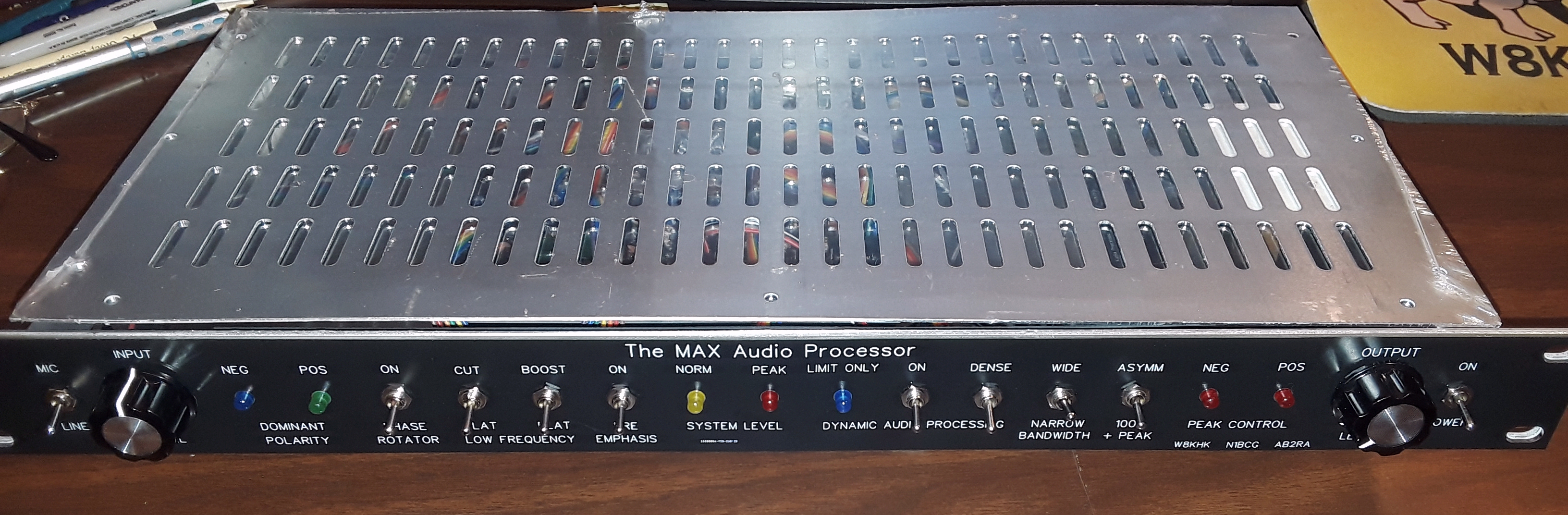
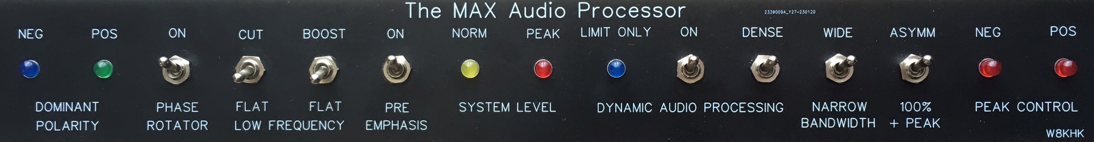
MAX Audio Processor - Connections, Controls, and Indicators


RACK MOUNT PANEL SHOWN

Two inputs provide users with the ability to connect a wide range of Hi-Z, Lo-Z, balanced, unbalanced microphones, and line level equipment. The LINE/MIC input mode can be set using an on-board jumper. Both the MIC/LINE and second LINE input levels can be fully adjusted.

The basic model of the MAX Audio Processor features an input control and two LEDs that show normal (yellow) and peak (red) levels. An additional pair of LEDs indicate whether the polarity of the incoming waveform is predominantly positive (green) or negative (blue). This is useful for those who want to check the performance of their microphone(s).

A novel "Dynamic Processing" feature optimizes transmitted audio by maximizing just the desired audio and not background noise. The action of the Dynamic Processing is indicated by a blue LED.

The MAX Audio Processor includes comprehensive waveform processing to ensure loud and clean audio at all times. This is accomplished with a combination of asymmetry control, presence frequency enhancement, average audio maximization, and peak control. Users can tailor the sound instantly to suit preference or band conditions with the "OPEN/DENSE" switch or add optional controls for maximum flexibility. See the Customizations section for details.

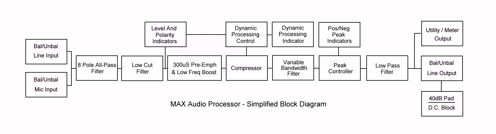
The heart of the MAX Audio Processor is the dual section precision SCAF (Switched Capacitor Active Filter) bandwidth limiting circuit. The three default switch-selectable sharp cutoff frequencies are 3kHz, 5kHz, and 7kHz (6kHz, 10kHz, and 14kHz bandwidth) although users can adjust any or all three using the internal trim pots. This allows instant selection of transmitted bandwidth to suit changing conditions. Alternatively, users can add an external potentiometer for continuous frequency response/bandwidth control. See the Customizations section for details.
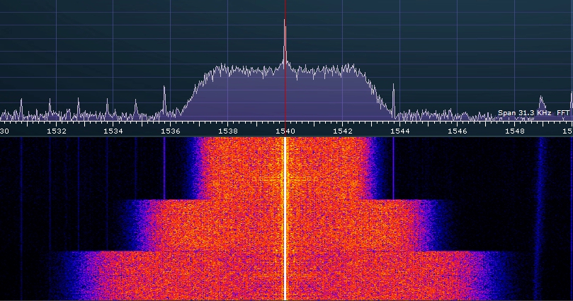
Two internally adjustable gain outputs can be configured for balanced or unbalanced line level (0 to +4dBu) or microphone level (-50dBu) to drive virtually any type of transmitter. An additional internally adjustable gain utility output is provided for connection to a VU meter or headphones if desired.

MAX Audio Processor - Circuit Description

  • Mic/Line Level Input - This versatile input uses an ultra-low noise SSM2019 pre-amplifier and can be configured as either mic or line level and connected to either balanced or unbalanced sources. Note that while microphones requiring “phantom” power may be used with the MAX Audio Processor, there is no 45 volt supply included in the design. An external phantom interface device is recommended in this case.

  • Line Level Input - An additional line input is provided to interface to other audio gear or receiver output for aircheck activities and can be connected to either balanced or unbalanced sources.

  • Dominant Polarity Indicator - Two LEDs show the dominant polarity of the source audio. The blue LED illuminates when the negative polarity is greater than the positive polarity. Reversing the + and - connections to the balanced input would flip this so that the green LED would now be on more of the time. These indicators typically alternate even with microphones "phased correctly" due to the complex nature of speech waveforms. The All Pass Filter described below uses a proven circuit to address this phenomenon and cleanly maximize modulation.

  • All Pass Filter/Phase Rotator - This function has been a part of every broadcast audio processor since the 1980s due to its ability to increase average modulation levels without changing gain. Compressors reduce gain based on the higher of either positive or negative peaks so asymmetrical waveforms, common with speech, cause unnecessary gain reduction. By rotating the polarity of the incoming signal throughout its frequency range, the overall waveform becomes more symmetric, resulting in less gain reduction (louder audio). The circuit is referred to as an all pass filter because it is acoustically transparent unless the speaker is wearing headphones. In this case, the effect can be heard since the path of audio to the ears through the jaw and from the headphones will be neither in nor out of phase. Some detailed information is available here.

  • Low Cut Filter - Also known as a "high pass filter" this circuit attenuates frequencies below the communications vocal range. Background noise such as rumble or vibrations from amplifier fans and power supplies are significantly reduced with this feaure enabled. It has the added benefit of enhancing clarity when the MAX Audio Processor is set for narrow bandwidths by allowing the important 300-3000 Hz vocal range to be emphasized.

  • Low Boost Filter - Some microphones attenuate lower vocal frequencies, and while this is important for use in noisy locations such as when operating mobile, it can result in an unnaturally "tinny" sound in a quiet location. Turning on the Low Boost will help flatten the frequency response below 250 Hz although this is not recommended when using narrow bandwidth settings.

  • Pre-Emphasis - This active R/C circuit uses a 300uS time constant to provide sufficient boost in the important vocal range. It is normally enabled to counteract the inherent loss of higher frequencies by narrow bandwidth receivers and to improve the signal to noise ratio and intelligibility.

  • NORM and PEAK Level Indicators - The MAX Audio Processor is designed to accommodate source audio with a wide dymamic range as is typical of speech. The input level is optimized using a setting that causes the yellow NORM LED to be on while talking while the red PEAK LED should only ocassionally flicker. This is also the ideal level when using the Dynamic Processing feature described below.

  • Dynamic Processing - Most common audio processors simply reduce gain at high input levels and increase gain at low input levels. This results in excessive background noise and the "compressor breath" sound where inhaling between words is emphasized. Transmitting a signal with a low signal to noise ratio reduces intelligibility, particulary when reception is poor.

    The MAX Audio Processor offers a unique Dynamic Processing mode that applies the desired amount of compression -only- when there is audio to be processed. This reduces background noise by preventing any increase in gain when the input to the MAX processor drops below a preset level as indicated by the illumination of a blue LED.

    At this point, the gain of the compressor "freezes", neither increasing or decreasing. This is very different from expanders or noise gates and provides a very natural transition from ambient audio to active audio to be optimized for transmission.

  • Compressor - The compressor section is designed to provide effective transmitted audio control. User selectable settings range from a mellow "Open" sound for casual conversations during good band conditions to a significantly aggressive "Dense" mode for challenging conditions and contesting. Even this setting maintains enough dynamic range to preserve "sonic cues" that aid in intelligibility.

    Unlike off-the-shelf audio processors that use both the negative and positive half of the audio waveform to develop a gain reduction control voltage, the MAX Audio Processor uses just the negative half of the audio waveform. This ensures that the finite range of negative modulation is maximized by preventing asymmetric positive peaks from causing excessive gain reduction, an important characteristic of fully modulated AM. However, the circuitry for fullwave control is included and can be utilized for FM use with the addition of a single diode.

  • SCAF Adjustable Bandwidth Filter - Bandwidth is controlled by two MAX295 SCAF (Switched Capacitor Active Filter) chips wired in tandem. This arrangement provides a moderately steep rolloff of frequencies above the set point while minimizing audible artifacts. The filter frequency is determined by a three position switch, offering 3, 5, and 7 kHz frequency response (6, 10, and 14 kHz bandwidth). These frequencies can be changed by the user for full customization.

  • +/- Peak Controller - This circuit features separate limiters for the positive and negative polarity peaks. Negative peak control is fixed while the positive peak control can be adjusted from symmetric (+100%) to asymmetric (around +130%). While this upper limit can be changed by the user, it has been demonstrated that peak energy beyond +100% contributes nothing to perceived loudness yet there is an increased risk of damage to modulation transformers and RF components due to exceeding component breakdown voltages.

    A demonstration of modulating to +100% vs +150% using an Optimod 9200 can be seen here: https://youtu.be/nVucVH0kNjc

    With excessive peaks in check, average modulation levels can be increased noticably before reaching -100% (AM), triggering an ALC cutback (SSB), or reaching maximum deviation limits (FM). This peak controller circuit features absolute -100% peak control and a user selectable +100% (all modes) or +125% (AM only) peak control.

  • Line Level Output - The line-level output can be configured as either balanced or unbalanced. A low-level connection for microphone inputs can be adjusted for proper level and polarity.

  • Utility Output - This single-ended high-impedance output has both a fixed level around 0dBM and an adjustable level.