| Revision Date: 250815
Information contained on these web pages copyright W8KHK / N1BCG. Amateur or individual use is encouraged. |
|
MAX Hacks: For those who like to experiment
No matter how much thought goes into design, there's always that "what if" wonder that drives experimentation. The MAX Audio Processor is based far more on "should" than "can" when it comes to performance, but as a kit with all common through-hole components and a modular design, it's also a great platform for total customization for those who want something unique of their own.
In this section we remove our narrow ties and put down the slide rules, and in a striking departure from better judgement, we offer the following for those less interested in "well behaved" and more interested in "off the leash". Proceed with caution...
Changing the pre-emphasis (MAX 540 and 540L)
Note that C29 (150pF) is used for limiting or "shelving" the boost so that it doesn't continue to increase above 10 kHz. This is important in order to maximize modulation levels which could otherwise be impacted by harmonic energy beyond the vocal range.
Changing the pre-emphasis (MAX 530 and earlier)
Increasing loudness
Changing the value of R101 from 20k to 10k results in greater "punch" by lowering the compression ratio and shifting more of the audio level management from the compressor to the limiter. The location of R101 will vary slightly depending on the model but should be close to the left edge of the circuit board near U101.
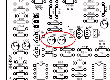
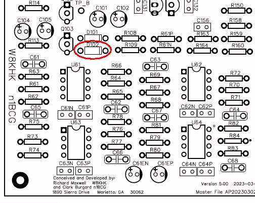
Accomplishing this is as simple as increasing the drive level to the limiter circuit by replacing C101 with a resistor. Note that C102 would also be replaced with a resistor if you are using D102 for FM transmission (see the section on Half-cycle gain reduction control below). This modification has the effect of lowering the amount of compressor gain reduction which results in a higher drive level to the peak limiter circuit and thus increases loudness.
We've found that a 4.7k resistance noticeably increases loudness while still sounding clean. Higher value resistances such as 10k and up will further increase loudness with a corresponding sacrifice in fidelity. It will be necessary to readjust the output levels after this modification. Adding a 10k potentiometer or trimpot will allow fine adjustment.
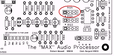
While the peak limiter circuit provides the same degree of peak control found in broadcast processors, some users may want even tighter control over negative peaks or to put a greater emphasis on loudness. The adjustment requires the connection of a digital voltmeter between the emitter of Q135 and ground (chassis). The emitter is the lead closest to the letter "N" of "Neg Peak Lim".
IMPORTANT NOTE: This function is intended to supplement the fixed negative peak limiter by using a setting that enhances the negative peak control. Using more aggressive settings (lower voltage measured at the emitter of Q135) will cause asymmetry by surpassing the fixed negative limiting action.
Dynamic noise reduction (All models)
As a clarification, this is different from the Dynamic Processing feature that was added beginning with the MAX 500. That function freezes the gain during pauses in speech which prevents background noise from being unnecessarily amplified. However, when the Dynamic Processor is disabled, the gain will increase dramatically at a rate set by the Density switch.
This modification decreases the high frequency gain during pauses which not only can help prevent feedback from monitor speakers or even headphones, but also reduces background noise. The addition of a 0.0047uF ("472") mylar cap in the C106 position (MAX 540 and 540L), or the R110 position (MAX 500) will add a high a frequency rolloff that increases with gain. This doesn't affect audio as long as the NORM indicator is active but will greatly reduce broadband noise pickup during pauses.
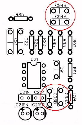
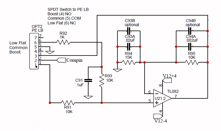
This isn't so much of a hack, but rather, a description of the difference between using both halves of the audio waveform to control gain reduction (compression) compared to using just one half. First, it's important to point out that this is *not* a mod to do if you use your MAX for FM transmission, a mode that benefits the most from symmetric deviation (modulation). However, half-cycle gain reduction control provides a significant loudness advantage to AM and SSB modes!
Gain reduction is typically achieved by using a full-wave rectifier to convert the A.C. audio to D.C. to control a VCA (Voltage Controlled Amplifier). The higher the D.C. voltage the lower the gain of the VCA and visa-versa. Using full-wave rectification ensures that the VCA responds to both the positive and negative halves of the audio waveform regardless of asymmetry. While this is a common feature of audio compressors, it does have a disadvantage where an asymmetrical waveform will cause more gain reduction than would occur with a symmetrical waveform. If you were to see this on a modulation monitor that could show both negative and positive modulation simultaneously, a positively polarized asymmetric modulating waveform would show less than 100% negative modulation, thus the importance of phase rotators, aka all-pass filters.
Wait! Is this just another lecture on symmetric modulation?
No, in fact it's just the opposite, incredibly. If the VCA responded *only* to the negative half of the audio waveform then the greater amplitude of the positive half of an asymmetric waveform would no longer drive the gain even lower. In other words, the gain of the VCA would maintain a regulated amount of negative modulation regardless of asymmetry in either polarity. Woo Hoo!
With this done, a positively polarized asymmetric waveform could gain several dB in perceived loudness. By contrast, a negatively polarized asymmetric waveform would have the same perceived loudness as when both halves of the audio cycle. It's now fairly important to ensure that your audio source (microphone) is connected so that the green Dominant Polarity LED lights up more than the blue LED in order to take advantage of this modification (click image for a larger view).
The dark secret of phase rotators
These all-pass filter circuits allow higher average modulation because they reduce excessive gain reduction caused by asymmetric audio.
The MAX Audio Processor utilizes an 8 pole phase rotator which provides the optimal amount of asymmetry cancellation by inverting the phase of the audio so that both lower and higher frequency asymmetry (which are typically opposite in polarity) cancel within their own frequency bands.
But what if instead of making the waveform symmetric, the asymmetric lows are inverted to match the polarity of the asymmetric highs? This would be the audio equivalent of nuclear fusion by creating "super-asymmetry" so we must handle this with care. Incredibly, a 2 pole phase rotator will do just that due to the reduced number of phase shifts.
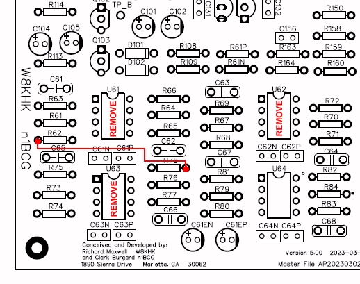
To do this on the MAX 500, remove ICs U61, U62, and U63 and add a jumper as shown in the image to the right (click for a larger view).
Continuously variable bandwidth
The earliest versions of the MAX Audio Processor had this feature although it was subsequently changed to switch-selectable presets. Being able to instantly "dial in" any bandwidth was an incredibly cool feature and made for some great on-air demonstrations but it required a calibrated dial. The option is still there and the process for converting to continuously variable bandwidth is fairly simple.
With the bandwidth switch removed, connect the potentiometer to the center and lower circuit board holes where the switch used to be. The other end of the wires would connect to the wiper (middle terminal) on the potentiometer and one of the outer terminals. The chosen terminal will determine whether the bandwidth increases or decreases depending on the direction the knob is turned. The most common is to have bandwidth increase with a clockwise turn. Usually this would mean using the outer terminal on the right when looking at the potentiometer from the front (shaft end).
Low cut filter cut-off frequency (Fc) change
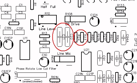
However, a user may want more aggressive reduction from a higher Fc when there is significant low frequency noise, limited bandwidth, or for a crisper sound. This can easily be done by replacing C21, C22, R23, and R24. The new values should be 0.047uF for both capacitors and 10k for both resistors to achieve an Fc of 450 Hz. Note that the board image shown is for the 510 series although the component numbers are the same for other revisions.
Deep cleaning "mud removal" filter
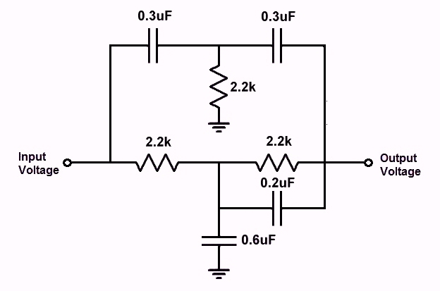
This medium-Q twin-T filter provides: -1 dB @ 62 Hz, -3 dB @ 94 Hz, -6 dB @ 290 Hz, -3 dB @ 440 Hz, and -1 dB @ 700 Hz, all referenced to 1000 Hz. The insertion loss is 4 dB. The additional 0.2uf cap is used for shelving to flatten the gain above 1000 Hz to 0.5 dB
Ideally this should (and probably will) be placed after the phase rotator, but it can easily be added as an external circuit to the line input. For unbalanced inputs, the circuit is simply placed inline with the audio. For balanced inputs, the circuit is placed inline with the + lead and the ground (or common) connects to the - lead.
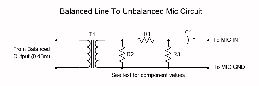
Ground loop hum and noise
This isn't so much of a hack as it is a suggestion for eliminating ground loop hum or other noises when connecting the MAX output to an unbalanced input, such as a microphone input. The MAX is equipped with a low level output with a D.C. blocking option for this purpose but in some cases it is not possible to connect the audio ground connection on a mic jack to the shield of the cable from the MAX without getting ground loop noise.
The circuit shown below uses an audio isolation transformer followed by an attenuator and then a D.C. blocking capacitor which will effectively couple the high level (0 dBm) balanced output of the MAX to an unbalanced microphone input.
A Final Word regarding Customization, Troubleshooting, and Support
The Max audio processor was developed by several amateurs in spare time over the past two years, with many revisions and refinements. They have performed on-air testing, evaluated various components in the mix, and arrived at a point where it is believed that the results should be shared. If assembled as recommended in these documents, without extraneous customizations, the device should provide excellent performance. That said, the kits are being made available at cost-of-components plus just enough to recover handling, shipping, tax, etc.
Additional effort has been expended to provide as thorough documentation as possible. The kits are offered "as-is" with no implied warranty or support. With the modular interfaces, it should be very easy for any amateur to trace the signal through any of the modules, isolate problems, and identify any parts issues. Through numerous component changes, the circuit boards have stood up to extensive soldering and de-soldering without any quality issues. It is hoped that the availability of this device will bring satisfaction to the builder and pleasure in operating on the ham bands. We look forward to hearing your call and working you in the near future. |
|||||||||||||||||||||||||||||||||||||||||||||||||||||||||||||||