- Initial Settings
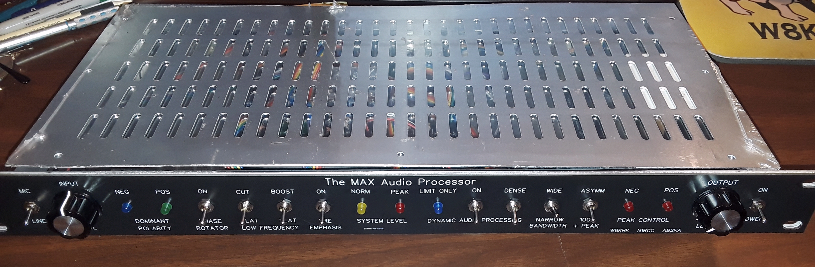
MIC/LINE: Line (or internal jumper INSW to "Line")
PHASE ROTATOR: Off
LOW FREQUENCY: Flat, Flat (Cut & Boost Off)
PRE EMPHASIS: Off
DYNAMIC PROCESS: Off
DENSITY: Dense
BANDWIDTH: Wide
+PEAK: 100%
Power: On
- Dynamic Processor Mode Test
1) With no signal input, turn on DYNAMIC PROCESSING.
2) The blue LIMIT ONLY LED should illuminate.
3) Turn off DYNAMIC PROCESSING.
- Initial System Function Checks And Level Settings
1) Connect a VU meter or A.C. voltmeter with VU scale between test point "TP L" and chassis ground.
2) Connect an audio signal generator to the line input. If unbalanced, connect hot to the + input and shield to both - and ground.
- Level Indicator Check
1) Set the audio signal generator output to 400Hz at 0dBM
2) Verify that the input switch or INSW jumper is set to LINE
3) Adjust LINE INPUT level for "0 dBm" (0 VU) on the meter. The yellow NORM LED should be on.
4) Reduce the audio signal generator output until the NORM LED extinguishes. This should occur around -8dBM.
5) Increase the audio signal generator output until the PEAK LED illuminates. This should occur around 6dBM.
- Equalization Check
1) Set the audio signal generator output to 400Hz at 0dBM.
2) Adjust LINE INPUT level for "0 dBm" (0 VU) on the meter. The yellow NORM LED should be on.
3) Turn PHASE ROTATOR on. The VU meter should read between -1 and 1dBm. Turn PHASE ROTATOR off.
4) Set the audio signal generator output to 100Hz at 0dBM.
5) Turn LOW CUT on. The VU meter should read between -4 and -5dBm. Turn LOW CUT off.
6) Turn PRE EMPHASIS on to enable LOW BOOST.
7) Turn LOW BOOST on. The VU meter should read between 2 and 3dBm. Turn LOW BOOST off.
8) Reduce the audio signal generator output to -10dBm at 5kHz. The VU meter should read between -1 and 1dBm.
- Microphone Input Check
1) Set the audio signal generator output to 400Hz at -60dBM.
2) Connect the audio signal generator to pins 2 (+) and 3 (-) on the microphone input. If unbalanced, connect hot to pin 2 (+) and shield to pin 3 (-).
3) Verify that the input switch or INSW jumper is set to MIC and the Mic Input Gain Set jumper is closest to the board edge.
Note: If a gain trim pot is used at R16 instead of a fixed-gain jumper, skip to step 6.
4) Adjust MIC INPUT level for "0 dBm" (0 VU) on the meter. The yellow NORM LED should be on.
5) This is a good level starting point for most dynamic microphones. Ignore the following steps, needed only for the variable gain trim option.
6) Set the MIC INPUT level control to 60 or 70 percent (about 2 o'clock).
7) Adjust the gain trim pot R16 for "0 dBm" (0 VU) on the meter. The yellow NORM LED should be on.
8) This is a good level starting point for most dynamic microphones.
- Compressor Check
1) Connect an audio signal generator to the line input. If unbalanced, connect hot to the + input and shield to both - and ground.
2) Set the audio signal generator output to 400Hz at 0dBM.
3) Verify that the input switch or INSW jumper is set to LINE.
4) Connect a VU meter or A.C. voltmeter with VU scale between terminals 2 (+) and 3 (-) on main output.
5) Adjust output level (trimpot R181) for a reading of "0 dBm" (0 VU) on the meter.
6) Increase the audio signal generator output to 10dBm. The VU meter should read between 0 and 1dBm.
- Frequency Response Check
1) Set the SCAF jumper to bypass the SCAF (not on pins marked with __ )
2) Set the audio signal generator output to 400Hz at 0dBM.
3) Adjust LINE INPUT level for "0 dBm" (0 VU) on the meter. The yellow NORM LED should be on.
4) Sweep the audio signal generator from its lowest frequency setting up to 5kHz. The output should remain within +0dB and -3dB.
5) Increase the audio signal generator frequency to 10kHz. The meter should show a loss of 7dB.
- SCAF Bandwidth Filter Check
This procedure sets the maximum frequency response of the transmitted signal. The bandwidth will be the same as the frequency response for SSB transmissions and 2x the frequency response for AM transmissions. For example, if you want a maximum AM bandwidth of 10kHz then use a frequency response of 5kHz.
1) Set the SCAF jumper to activate the SCAF (on pins marked with __ )
2) Set the audio signal generator output to 2kHz at 0dBM.
3) Adjust LINE INPUT level for "0 dBm" (0 VU) on the meter. The yellow NORM LED should be on.
4) Set the BANDWIDTH switch to NARROW.
5) Increase the frequency of the audio signal generator and note when the output level drops to -20dB. This is the current narrow bandwidth setting. Use trimpot R123 to adjust the cutoff frequency either lower (counterclockwise) or higher (clockwise). Verify the -20dB cutoff by sweeping the audio signal generator frequency around this setting.
6) Set the audio signal generator output to 2kHz at 0dBM.
7) Set the BANDWIDTH switch to MED (medium).
8) Increase the frequency of the audio signal generator and note when the output level drops to -20dB. This is the current medium bandwidth setting. Use trimpot R124 to adjust the cutoff frequency either lower (counterclockwise) or higher (clockwise). Verify the -20dB cutoff by sweeping the audio signal generator frequency around this setting.
9) Set the BANDWIDTH switch to WIDE.
10) Increase the frequency of the audio signal generator and note when the output level drops to -20dB. This is the current wide bandwidth setting. Use trimpot R125 to adjust the cutoff frequency either lower (counterclockwise) or higher (clockwise). Verify the -20dB cutoff by sweeping the audio signal generator frequency around this setting.