Revision Date: 200418 v4
Information contained on these web pages copyright W8KHK / N1BCG. Amateur or individual use is encouraged.
Commercial use of any kind is prohibited without the express written permission of the author, Richard A. Maxwell
Max Audio Processor - Calibration
Users can make changes to suit personal taste, but the following are how the MAX Audio Processor is supposed to be set for optimal results.
- Polarity Indicator Balance
Input: Pin 1 of "PETP" test point header - Connect a signal generator set for 1 kHz @ 0dBm (775 millivolts RMS, 2.2V PtoP @ 600Z)
Note: To prevent loading the test generator signal, there must be no connection to Pin 3 of "APF" header while this adjustment is performed.
Output: n/a
This is the point, or close to it, that the yellow "Norm" LED should be lit. Adjust R168 (Balance) so that both the + and - Polarity LEDs are both on. This is a very sensitive adjustment.
The adjustment may also be made measuring the comparator input (LM339 U152, pins 4 and 7) with a dual-input oscilloscope set for differential mode. Adjust for null, such that both signals are equal in level.
- Clipper Drive
Input: Pin 1 of "PETP" test point header - Connect a signal generator (1 kHz @ -12dBm)
Output: Pin 4 of "CLPTP" test point header - Connect 1M oscilloscope input (500uS/div)
Note: To prevent loading the test generator signal, there must be no connection to Pin 3 of "APF" header while this adjustment is performed.
Using either jumpers or front-panel switches, the following conditions must be met:
1) "PE" header must have pin 3 connected to pin 4 (Pre-Emphasis enabled)
2) "CMP" header must have pin 3 connected to pin 4) (Compressor/Limiter enabled)
3) "Compressor Options" header must have pin 4 connected to pin 5 (Compress mode selected)
The amount of clipping to use is subjective and these settings are considered a good starting point. Adjusting R202 (Clipper Drive) will provide up to 1.9V PtoP as shown on the oscilloscope. This represents fairly aggressive clipping. Setting R202 for a 1.3V PtoP is fairly light clipping. While the amount of clipping change seems large for a very small change in voltage, the limiter function of the SSM2166 maintains a constant clipping level over a wide range of input levels.
A good starting point is around 1.6V PtoP
- Bandwidth Adjustment
Input: (n/a)
Output: Place the pickup loop or probe of a frequency counter (or receiver that can tune 100-400kHz) near U131 the 555 timer chip.
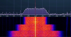
The MAX features three preset bandwidths of Narrow (6kHz), Medium (10kHz), and Wide (14kHz). These values represent the space occupied by the modulated carrier and are twice the audio frequency response for each setting. Narrow is comparable to many commercially produced amateur radio transmitters (6Khz bandwidth/3kHz audio) and is considered a minimum.
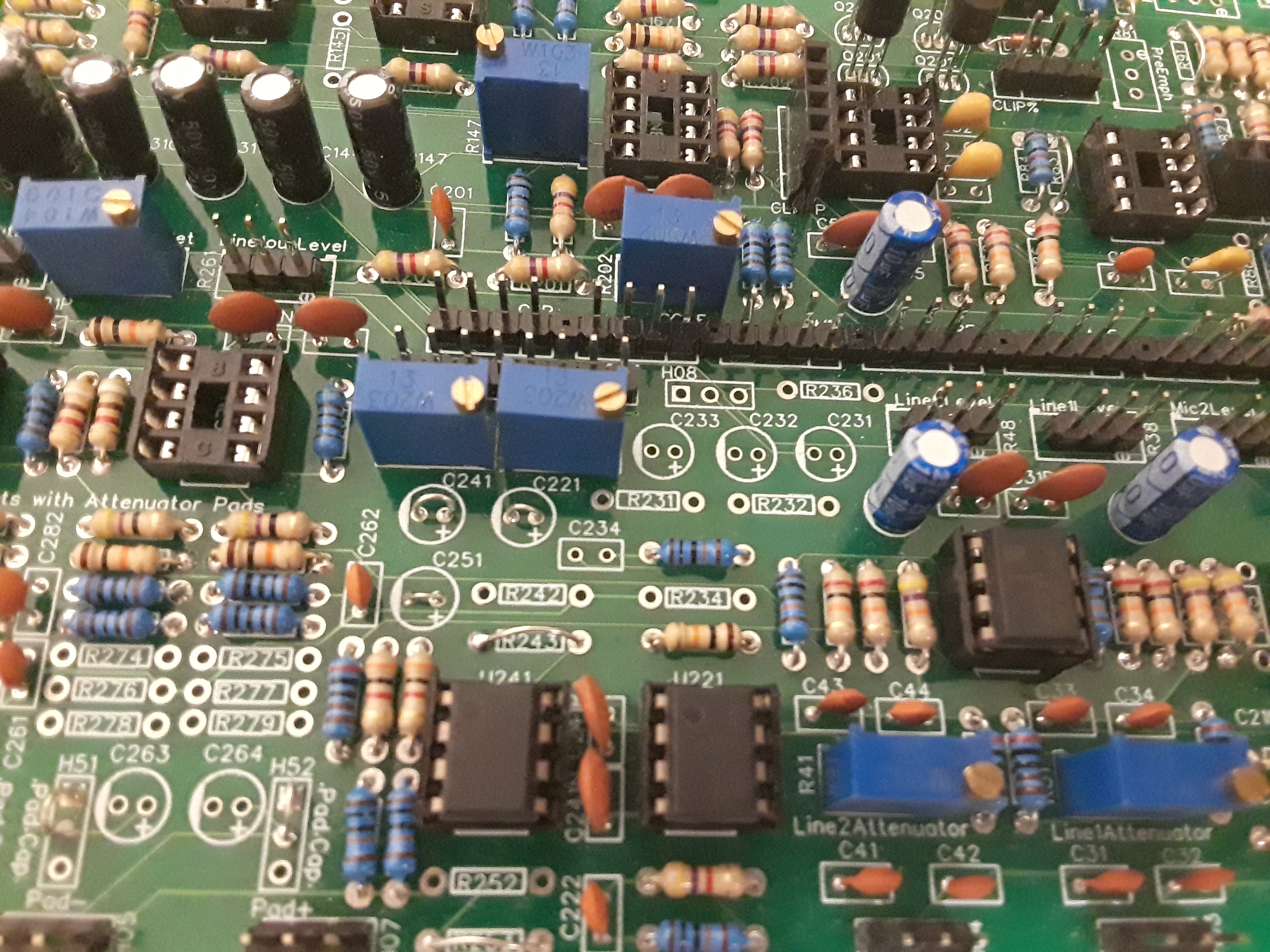
Users who wish to set their own bandwidths can do so by adjusting trimpots R136 (Narrow), R135 (Medium), and R134 (Wide). An accurate setting requires measuring the clock frequency of the SCAF filters (U141 and U142) which operate at 50 times the audio response frequency. This can be done using a frequency counter or communications receiver with a short pickup wire for an antenna placed near the circuit board and adjusting the trimmers for the desired frequencies.
This chart shows the relationship between audio frequency response, total bandwidth, and clock frequency:
| Audio Response |
3 kHz |
5 kHz |
7 kHz |
| Total Bandwidth |
6 kHz |
10 kHz |
14 kHz |
| Clock Frequency |
138 kHz |
225 kHz |
323 kHz |
|

|
Another method for adjusting the bandwidth filter uses a tone oscillator connected to the line input and a VU meter connected to the Utility output. Set the oscillator for 1kHz at a level between -10dB and 0dB (or any convenient level that lights the yellow level LED but not the red one). Set the Utility output level trimmer (R251) for 0dB on the attached meter. Set the oscillator for the desired frequency of filtering and adjust the appropriate trimmer (as descibed above) for 3dB of loss. Increasing the oscillator frequency will show the filtering as a reduction of audio level.
|


