 |
 |
| The MAX Audio Processor For Amateur Radio, LPAM, And Podcasting | |
| HOME ||| GALLERY ||| ASSEMBLY ||| CALIBRATION ||| CONNECTIONS ||| MODS ||| SCHEMATICS ||| AVAILABILITY ||| CONTACT ||| LEGACY INFO |
| Revision Date: 230912
Information contained on these web pages copyright W8KHK / N1BCG. Amateur or individual use is encouraged. |
|
The "MAX" Audio Processor Assembly Information - General Guidelines
Read this section BEFORE proceeding with component insertion and soldering. It is necessary that the builder review the entire MODS and CUSTOMIZATION section (appearing later on this page) before starting construction. The choice to install headers or trim-pots, and other components, is dependent upon the builder's preferences for controls and other options! There are cases where a part value may vary, depending upon desired features, so building strictly from the parts list will NOT produce a properly functioning product.
Three versions of the parts list (identical in content, different sequence), and a Bill of Materials, are provided. Click the links below to access these files.
A) Organized by Component Value: for parts acquisition and inventory (Actually, this is the most efficient way to populate the audio processor board, as described in the "Build Suggestions" below.)
B) In sequence by Component Number: for careful verification of component locations on PC board (This list makes it easy to correlate proper part value for each component number, rather than needing to refer directly to component values on the schematic diagram sheets.)
C) Grouped by Function: to enable the inclusion or exclusion of processor modules
The Bill Of Materials with component values and counts will also be helpful to organize the inventory. There will be many extra, left-over parts when the build is completed, for three reasons:
Build Procedure Overview:
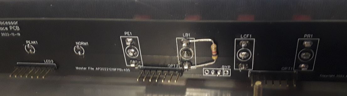
The "Legends" that identify component locations are arranged on the printed circuit board such that they are not covered, or hidden, by the components as they are installed. In order to avoid any confusion or ambiguity, the legends are consistently placed either TO THE RIGHT of the component, or DIRECTLY ABOVE the component, depending upon where space is available for the legend text. As an additional aid in locating components by number, you may wish to either photocopy the board silkscreen, and keep a printed copy as you assemble. Optionally, you may be able to print an image of your board from the MAX website. In this case, be CERTAIN that the board revision number and board date code on the printout match the board you are building.
Diodes should be installed before resistors, such that risk of inadvertently installing one type device in the other type's location, is minimized.
When installing resistors, or other color-coded components, it is much easier to trace and troubleshoot issues after assembly, if all these devices have their color code orientation either top to bottom, or left to right. All resistors with a tan background are carbon composition, four color bands: digit one, digit two, a multiplier, and a tolerance band from left to right. The resistors with a blue/green background are metal film resistors, having five color bands: digit 1, digit 2, digit 3, a multiplier, and a tolerance band. Either type resistor may be supplied and used anywhere in the processor with identical performance.
Inserting and Soldering components:
The easiest and quickest (but not the best) method is to insert the device, solder both leads, then trim the excess wire leads. A better, more professional and reliable method consists of a few additional steps. First, insert the resistor, and solder one of the wires. Invert the board (after soldering one wire of several resistors, if desired) and ensure the resistor, or other device, is flush with the board surface. Now trim both leads, solder the unsoldered lead, then go back and reheat/resolder the first soldered lead.
This technique provides several benefits: It ensures a neater layout, with all devices close to the board; it avoids any risk of a cold solder joint, where the first solder connection could be compromised if the component moves while solder is cooling; soldering after trimming the wire ensures the solder contacts the bare wire where it is cut, guaranteeing a no-loss contact, and last but most important, there are no sharp points that are uncomfortable when handling the board, and the contacts will not protrude and touch a metal enclosure if they are all trimmed carefully before soldering.
This technique applies to all wired components, including trim pot leads. Non-wired components, such as dupont or berg pin headers, JST connectors, IC sockets should NOT be trimmed, either before or after soldering. When installing IC sockets, first solder only the two diagonally-opposite pins (pin 1 and 5 on an 8 pin device) then invert the board to ensure the socket is flush with the board. If not, reheat the pin, push the socket flush, then solder the remaining pins. For strings of dupont or berg header pins, solder just ONE terminal, then make sure the assembly is flush with the board AND vertical in both planes, before soldering the remaining pins. After all soldering is completed, solder flux may optionally be removed with a spray or brush-on removal chemical, but this is not required for proper device performance.
Build Procedure Suggestions:
The easiest and most efficient way to populate the board is to use the "Component Value" spreadsheet as a guide, inserting all components of the same value in each component location, in sequence by device number. Each section of the circuit has a different component number prefix. In MOST cases, all the resistors, capacitors, etc. within a given prefix may be located near the integrated circuit chip with the same prefix number.
Before starting the assembly process, a review of the options will reveal the minor edits that need to be applied to the parts list. When choosing an option, the required value of the related part will be detailed. Simply refer to the parts list, and either circle the desired value part, or cross through the undesired value part. Then, as the board is populated, only the appropriate components will be installed for each selected optional feature.
Since you have read the documentation before you started building, you will know which parts strategy you wish to follow, therefor you will know whether to edit the "component by value" list, to install all like parts as one step, or perhaps the "part by component number" list, to populate a given functional section as a major build step. This is important such that you make your option preference annotations on the parts list that you will use while populating the board.
All of the smallest devices should be installed first (resistors, diodes, etc) followed by Integrated circuit sockets, then male and female headers. Smaller capacitors next, transistors, then electrolytic capacitors. LM series regulators should be installed last. This technique allows you to place the board up-side-down while soldering, thus holding the parts in place.
Here is the preferred sequence, which will avoid access conflicts, as well as make it much easier to install parts flush with the surface of the board.
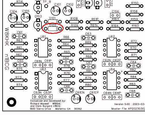
1) ALL diodes (carefully observing polarity - cathode stripe on diode matches stripe on silkscreen) except for D102 if you intend to use the MAX processor for AM or SSB. This is explained later in the "Gain Reduction Detection" section in MAX Audio Processor - Setting It Up below.
2) All resistors
3) All integrated circuit sockets
4) All disc ceramic bypass capacitors (.1 uF capacitors with part number suffixed either N or P.)
5) All Dupont header pins and JST connectors (These all require careful study of the options, as they relate directly to which controls you wish to have on the front panel, as opposed to those using trim-pots on the main board)
6) In ALL cases, Berg pin headers will be installed at the following locations:
DC1, DC2, DCIN, OUT, UTO, OPT1, OPT2, OPT3, LED3, BW, SCAF, and CMP.
You may choose to use either berg pin headers, JST connectors, or direct wire at locations:
LINE, MIC, and INSW.
You may choose either Berg pin headers, JST connectors, direct wire, or trim pots at locations:
R10 (line input level), R12 (mic input level), R180 (utility output level) and R181v (main output level).
7) All ten-turn blue trim pots. Note: Be sure to use either a trim pot at R152V, or a fixed resistor at R152, but DO NOT install both components.
8) All transistors (DO NOT mount transistors flush with the board; instead allow about 3/8" lead length above the circuit board)
9) All other disc and mylar capacitors
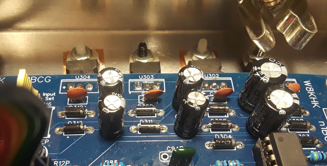
10) All electrolytic capacitors, being careful to orient with proper polarity. The longer lead is positive, and the negative side of the capacitor and the silkscreen have silver or white shading. In most cases, all the electrolytic capacitors are oriented in the same direction.
11) All three-terminal voltage regulators. Keep the leads about 3/8" to 1/2" long. You may use either individual heat sinks, or sink to the back of the enclosure, while ensuring the negative (U302, U304) regulators are insulated from the metal enclosure. In most cases, it has been found heat sinking of the regulators is likely not necessary.
Component Number Nomenclature:
Most components are identified by a single letter followed by a sequence number, for example R1 is the first resistor as seen on the schematic diagram. If the parts list indicates a suffix, such as R5A, R5B, R5C, etc, please check the optional build instructions to determine which value to install to achieve your desired results. Only one of the resistors will be used.
The processor employs extensive power supply decoupling and filtering to provide noise and hum free operation. Each integrated circuit will have one or more disc ceramic capacitors to bypass each power rail. The capacitors associated with chip U11 will be identified as C11N and C11P, which are simply the negative and positive power supply sources for this chip. These are NOT to be confused with C11, which may or may not exist.
The same nomenclature method is applied to the decoupling resistors, R11N and R11p. If the chip also has one or two electrolytic capacitors in its vicinity, those capacitors will be identified as C11EN and C11EP. All components with no such letter suffix are actively involved in the signal circuits and are not related to power distribution, with the exception of components in the 3XX series, which are parts comprising the power supply.
Customization Options - Must Review BEFORE starting the main board assembly and soldering task
Control Options - panel mounted switches, or fixed jumpers?
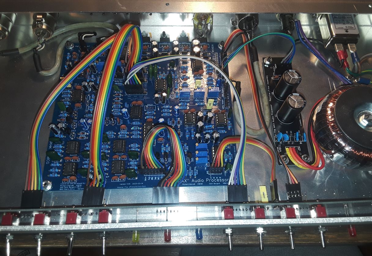
In most cases, the typical operator would prefer to have all optional settings available on the front panel. Earlier versions of the processor required the builder to solder individual wires between the main board and the terminals on all switches and indicator LEDs on the front panel. Starting with revision 500, the builder may select the optional front panel kit, which includes a drilled and silkscreened dress panel, all switches and LEDs, and a custom "front panel interface" printed circuit board, to which each switch and LED is soldered.
To complete the interconnection to the main processor board, several prefabricated ribbon cables mate with plug pins on the respective boards. This method of construction virtually eliminates all manual point-to-point wiring requirements. There are several panel and interface PCB options which mate with various rack and desktop enclosures.
The builder may still wish to have a completely customized layout, in which case the dress and interface PC boards will not be needed. Guidance in wiring the switches and LEDs is provided in the "LED and Switch Front Panel Interconnect" Schematic Diagram sheet.
If the builder wishes to preset all processor options, including the input and output level settings, it is possible to populate the main board with trim pots for level settings, and apply berg jumpers to the male connectors which would otherwise be used to connect the ribbon cables to the option switches. This method would reduce the required number of interconnections, leaving only power, input, output, and possibly the LED indictors. When planning the customizations, any mix of switch and fixed jumper settings may be chosen.
An important note regarding "phantom power" for microphones:
The input circuits do not include any source of phantom power. If microphones which need phantom power are contemplated, it will be necessary to use an external source between the microphone and the processor. The rationale for this design decision focuses on minimizing the potential for expensive microphone damage due to variations in kit building.
NOTE: The designers of this device assume no responsibility for microphone damage if the builder attempts to add a phantom power source to the circuit.
Input circuit options:
Two separate input amplifiers are standard. Input one is typically used for a low-impedance balanced microphone, but it may also be used as a high-level, low-impedance line input. Input two is normally used as a low-impedance balanced line input, but it may be configured instead as a low-level, balanced microphone input. Both inputs support either balanced or unbalanced input connections.
In summary, the two inputs support either two microphones, two line inputs, or one of each input type. Signals from either input may be selected individually, either via a SPDT panel switch, or an on-board jumper. Mixing of two inputs simultaneously is not supported.
Input one configuration:
To use input one exclusively as a microphone input, populate R11 with a ten ohm fixed resistor and R16 with a 500 ohm trimpot. This allows the overall gain to be set; R16 is a gain trim adjustment.
To use input one alternately as either a microphone or line input, populate R11 with a 68 ohm fixed resistor, and R16 with a three-pin dupont male header, and use a berg jumper to select the input option. Jumper pin 1 to 2 for line level input, or jumper pin 2 to 3 for microphone level input.
Input two configuration:
To use input two as a high level balanced line input, populate R4, R5, R6, and R7 with 4.7K (4700 ohm) resistors, as shown on the schematic diagram sheet 1. To use input two with a microphone, populate R4 and R5 with 1K (1000 ohm) resistors, and R6 and R7 with 68K (68,000 ohm) resistors.
On both inputs, the MIC and LINE input header pin 1 is ground, pin 2 is positive, and pin 3 is negative. If using an unbalanced source, connect the shield to pin 1, the hot lead to pin 2, and connect pin 3 to ground pin 1. To reverse the polarity of the input device, connect the hot lead to pin 3 and connect pin 2 to ground pin 1.
Level control options
Fixed setting (trimpot) or variable setting (panel pot)
For operators who use the same microphone most of the time, the input level may be set permanently via the on-board trimpot. The compressor circuit provides sufficient dynamic range to cover normal variations in voice input level, so regular adjustment is unnecessary. In order to realize the benefit of the peak limiting circuitry in the processor, the output level must be set properly in accordance with the modulation level of the transmitter. If the transmitter does not require an input level adjustment when changing bands or output power level, then the processor output level might best be set with a trimpot and left indefinitely, thus avoiding inadvertently mis-setting the level by moving a panel-mounted output level control knob.
If either input or output level panel adjustment is desired, then either berg pins or JST connectors may be installed on the main board, enabling interconnection cables to run to variable resistors accessible from the front panel. Either an audio taper pot with a knob, or a one-turn trim-pot accessible through the panel, may be implemented using the front panel interface board with the 1U rack dress panel. This latter option may be interconnected with a three-wire dupont female-to-female cable, eliminating hand soldering of individual wires.
Mic/line switching options:
An option header labeled "INSW" is available to select between either line or mic input preamplifiers. For permanent or semi-permanent setting, install a male berg header at this location, and use the berg jumper to complete the circuit. If panel control of this option is desired, place a SPDT switch on the panel, and run the wires to this header, either via dupont or JST cable.
A single panel-mounted pot may be used to control the level of either the microphone or the line level input. When using the mic/line selection switch on the front panel, the common terminal of this switch may be connected to the panel-mounted level control, and the output of the pot would return the signal to the "INSW" header. A ground terminal for the pot is provided at pin one of header "INSW", the signal may be returned to pin 3 of the header, while pins 2 and 4 are the line and microphone signals selected by the NC and NO terminals of the switch. When wired in this manner, two more options are exposed.
If the line level pot location R10 andthe microphone level pot location R12 are populated with the berg pins, then jumpers may be placed from pin 2 to pin 3 of each jumper, thus allowing the front panel pot to have full control of each input level. Conversely, it is also possible to populate R10 and R12 with 10K trimpots, allowing the maximum input level to be defined by the trimpot, while the panel control provides easy adjustment, where the trimpots are set to a level where the main control might be set around 60% to 80% of full volume, thus eliminating the need to make a major adjustment to the panel level control when switching between line and microphone inputs.
Input and output cable and connector options:
Using JST v Dupont for multi-wire ins and outs: The input and output connections to the processor may be made to any type connector the builder chooses. Either XLR or standard 1/4" TRS (Tip-Ring-Sleeve, or phone connector) may be provided with the kit, as specified when ordering. Alternatively, RCA connectors, screw terminal strips, or other connectors may be mounted on the enclosure back panel, as desired. The wires to these connectors may be individually soldered at both ends, or a pre-fabricated dupont wire with berg pins, or a JST connector may be used.
JST are "Japan Solderless Terminal" connectors, whereby the male connector is soldered directly to the lands of the printed circuit board, and the female plug has multi-colored wires crimped at one end, while the other end may be pre-stripped ready for soldering. The JST connectors are polarized, meaning they can only be inserted one way, preserving the proper wire sequence when reconnected. While the JST wires are easy to solder, the dupont wires are very fine and hard to tin, so cutting and soldering the wires is not recommended. It is possible, in many cases, to use berg pins with male to female dupont wires, where the female end connects to the board-mounted bereg pins, and the male pin is soldered directly to the input or output connector pin.
Orientation of JST header: The JST connectors have notches to key the orientation of the plug in the socket, and the suggested position of the key side of the connector is toward the top, or back, of the main processor board. In this manner, the sequence of the colors of the various wires will be consistent, enabling accurate connection to switches, pots, or external connections. Pin one is almost always on the LEFT end of the header, but the silkscreen should be carefully inspected before completing this section of the wiring task. In almost all cases, the LEGEND that identifies the header is placed close to pin one. Where possible, a dot or period is also placed near pin one to identify pin sequence.
Bandwidth clock concerns:
Method of setting the various clock frequencies: The continuously variable bandwidth feature is implemented by two SCAF (Switched Capacitor Audio Filter) devices from Maxim. One filter device would be controlled by an external clock, the frequency being approximately 50 times the desired brick wall cutoff audio response. Two SCAF filters in cascade provide a much tighter, sharper cutoff, but require a slightly lower clock frequency for similar cutoff performance. The clock is provided by an NE-555 timer chip, using external capacitor and resistor values to set the duty cycle of the clock wave.
Specifications provided in the MAX Processor schematic sheet define the required clock frequencies for each of 3, 4, 5, 6, or 7 KHz audio response, resulting in the respective 6, 8, 10, 12, or 14 KHz occupied bandwidth of the transmitted AM signal. Adjustment up to 9 or 10 KHz audio response is possible, but the clock circuit design limits the possibility of much higher bandwidth settings. The design of the clock frequency switching provides either two or three different clock settings. A 10K ohm potentiometer could be used to provide continuous adjustment, in lieu of the switch. For three bandwidths, a center-off SPDT switch is used, while a standard SPDT switch offers just two settings.
Looking at the schematic diagram and the frequency chart, you will notice that R123 is connected for the lowest clock frequency, yielding the narrowest bandwidth, when the switch is positioned in the center-off position. For the medium and wider bandwidth positions, either R124 or R125 is switched IN PARALLEL WITH R123, providing the resistance necessary for the desired clock calibration. In concert with C123, the 1500 pF timing capacitor, the resistances needed for 3 through 7 KHz audio response are listed in the column to the right of the Clock Frequency column of the chart.
Clock Frequency Resistor Value Selection:
Examination of the chart reveals 8.2K is required for 3 KHz response, while 2.2 K provides 7 KHz response. If only two bandwidths are desired, either omit R123 from the board, or open the circuit on the bandwidth ribbon cable pin 2, or on the 1U rack version of the front panel interface PC board, remove the jumper from the 2-pin BW2 header, disconnecting R123 from the circuit. Now the narrow bandwidth will be determined solely by the value of R124, while R125 sets the clock frequency for the wider bandwidth, with the switch in the UP position. If you do not wish to go through any clock frequency or bandwidth calibration or measurement steps, simply install the fixed resistor of value 8.2K, 5.2K 3.5K, 3.0K, or 2.2K in board location R224 and 125, for the 3, 4, 5, 6, o 7 KHz audio response, as desired.
If you wish to have three settings, with the center off switch installed, and wish to use fixed resistors, refer to the right column in the chart, and install resistors 15K, 6.2K, 4.7K or 3.3K (any two, in locations R124 and R125, for medium and wide response will be a pair of either 4, 5, 6, or 7 KHz, while narrow is set with the standard 8.2K resistor at R123, with the BW2 jumper installed on the front panel interface PC board. Either of these methods, using fixed resistors, will put you "in the ballpark", and clock frequency will be very close to the calibrated value.
If you wish to calibrate the clock frequency to provide EXACTLY the brick wall frequency desired, install a 10K trimpot at R123, and either 15K, 10K, or 5K trimpots at R124 and R125. Select a trim pot that is LARGE ENOUGH to cover the values of resistance in the "VARIABLE (CALIBRATE)" column, and the result of these resistances in parallel with R123 will provide the correct clock frequency for each selected audio response frequency. If too low a value resistance is selected, then it may not be possible to adjust the frequency low enough. If a higher value than required trim pot is used, the adjustment procedure is touchy because the resolution of the resistance is small for a given range of turns of the adjustment screw.
Calibration of the actual clock frequency is covered in the adjustment and calibration section of the web.
General wiring and cabling options
Because the MAX Processor may be heavily customized, or built as shown in the examples on the web, voluminous details about the jumpers and their options are offered on the schematic diagram sheets. In addition, default jumper legends appear on the silkscreen next to most headers on the printed circuit board. This information may be used to either set permanent berg jumper options, or to wire switches in a custom fashion.
If the builder wishes to use any of the available silkscreened dress panels with the front panel interface PC board, there is no need to review or abide by any of these notations or legends. Simply assemble the front panel components to the interface PCB, and connect the provided ribbon cables between the front panel assembly and main processor board. Earlier versions of the processor and front panel included seven-pin headers for switches connected via OPT1, OPT2, and OPT3 headers. Only six pins are used, so either a six or seven pin ribbon cable may be used. The later versions of the board artwork provided only 6 pins.
To simplify assembly, it is suggested that only six-pin berg headers be soldered to pins 1 through 6 of locations OPT1, OPT2, and OPT3, leaving pin 7 hole (on the right) empty. The LED cable will require all seven pins to be connected by the ribbon cable. When connecting the ribbon cable from the front panel to the main board, pin one is ALWAYS on the left, when viewing the processor from the front; thus there should be no folds or flips in the ribbon cable, it should travel flat from the front panel to the board. When planning the physical layout of your processor, if not using a pre-drilled enclosure, it is IMPERATIVE that the main processor be positioned at a distance from the front panel such that the length of the ribbon cables allows easy reach and connection between headers.
Specific Cabling for revision 500 with the Front Panel Interconnect PC Board:
When using the front panel interface, the following cables must be interconnected: Either six pin, seven pin, or eight pin ribbon cables connect OPT1, OPT2, OPT3 headers between the main board and the front panel board. A seven pin or eight pin ribbon cable connects LED3 on the main board to LEDS on the front panel board (depending upon cable availability). In all cases where a wider-than-necessary cable is provided, it is important that pin one be matched to the same color wire at both ends of the cable. Location of the main processor board within the enclosure will be in part determined by the length (reach) of the OPT1, OPT2, and OPT3 cables.
A four pin cable connects the BW circuit. Short 20 mm ribbon cables may be provided for LEDs and BW, while longer, 40 mm ribbon cables are normally used for the other panel interconnects. A three or four pin cable is used to connect the DCOUT1 header on the main board to the POWER header on the front panel. There may be either a three pin or a six pin POWER connector on the front panel board, depending upon the board revision. Only three wires are needed, pin 1 is -5 volts, pin 2 is ground, and pin 3 is + 5 volts. These voltages are used by the PEAK CONTROL LEDs. If this cable is inadvertently connected with the polarity reversed, no harm is caused, however the PEAK CONTROL LEDs will not function until the error is corrected.
While this header indicates the negative and positive terminal locations, the main board is polarity-protected, so orientation of this connector is not critical.Inputs to the MIC and LINE headers consist of grounded pin 1, positive pin 2, and negative pin 3. In order to minimize ground loops, it is preferable to ground the main processor to a single point on the enclosure near or at either input connector, via a single wire to the GND terminal between the LINE and MIC headers. In addition, it is acceptable to ground the main processor board via the four mounting screws. If SAE 4-40 machine screws are used, the mounting holes in the PC board may need to be enlarged. In this case, the separate ground wire described above is imperative.
All input and output connectors should be grounded to the enclosure, but no other ground wires are needed between these connectors and the enclosure. JST connectors may be most convenient for theLINE, MIC, INSW, and any front panel control pot wiring, however the berg pin connectors are prefered for the output OUT and UTO termination, such that individual dupont wires may selectively connect to the pins as required.
Powering the MAX processor
The MAX Processor requires a low voltage A.C. supply (not included). Information about power supply options can be reviewed near the bottom of this page.
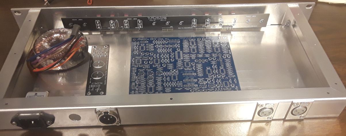
Enclosure options
For the small and mid-sized enclosures, we found Circuit Specialists of Tempe, AZ, provides a nice looking, well fitting solution. In single unit quantities, the shipping and handling can get expensive. We have a limited number of each of these enclosures available for shipment, and the cost will be linked to the variable cost of acquisition. Optionally, for a nominal charge, we may also offer to perform the necessary drilling and metalwork to provide you with a complete kit solution, should you not have the resources or experience to do this type of metal fabrication or preparation.
Board Verification and Testing
The board should be carefully inspected, visually, for any solder shorts or unsoldered connections. Then several ohm meter checks will verify there are no power circuit shorts. Once it is determined the board is safe to apply power, any and all of the individual circuit sections may be "performance verified" with the aid of an audio generator, oscilloscope, and AC voltmeter or DVM.
By placing the berg jumpers on the various headers, the circuits may be interconnected for a full function test, before installation in an enclosure and attachment of the front panel controls.
Conversely, after visual inspection, the enclosure and panel may be completely assembled, and testing performed on the finished product. If any issues arise, it may be necessary to remove the main board from the enclosure to address any circuit or solder issues.
Before applying any power
It is suggested that initial continuity or resistance checks be performed on the DC power rails. On a low resistance range, say 200 or so ohms, a DVM may be used to check for shorts between system ground and the AC input terminals, and the regulated -5, -12, +5, and +12 volt buses at the header on the top right corner of the board.
Since almost all sections of the circuit are decoupled from the supply rails (for minimum hum, noise, or unwanted interaction between circuits) it is beneficial to check for short circuits at almost every IC socket power terminal. Looking at the board from the top, the notch for each chip is to the top, so pins are numbered 1 to 4 or 7 from top left to bottom left, and the remaining pins through either 8 or 14 from the bottom right to the top right on each chip socket.
Starting with the 5 volt circuits, measure from ground to:
First test with power applied
Initially verify the -5, -12, + 5, and +12 volts on the power bus connector at the top right corner of the board. Optionally verify all the above voltages at the chip sockets before installing the integrated circuits.
After ICs are installed, the voltages measured on the power pins may be slightly lower than the supply rails, due to voltage drop in the decoupling circuits. This is normal and may be ignored. Insert the integrated circuits.
Board is now ready for testing with audio signals, if desired.
Preparation of the front panel "sandwich"
Earlier methods, now somewhat obsolete, but still available for complete freedom of design:
Earlier versions of The MAX Audio Processor provided the control and indicator components (Switches, variable resistors (pots) and Light Emitting Diodes (LEDs) such that the builder could design and fabricate their desidred front-panel layout. Alternatively, they might want to predefine all their option settings and levels, using the on-board trim pots and berg jumpers placed selectively upon the dupont header pins. New with the Series 500 MAX is an integrated control panel, where the builder may choose from a variety of panel layouts, either the 19 inch 1U rack, or a smaller desktop format. Two desktop versions of the panel provide for a very small (11.75" by 2") panel, or a somewhat larger (11.8" x 3") panel, with the matching aluminum enclosure.
The new Integrated "Sandwich" Interface Method
This was indeed a tedious and error-prone task. While the builder may still prefer this degree of customization latitude, now available are the pre-fabricated dress panels, composed of the same G-10 glass-epoxy printed circuit board material used in the main processor board manufacture. These panels are pre-drilled for the controls and indicators, the solder mask layer finished in either black for the rack version, and blue for the desktop options, with appropriate legends imprinted in sharp, clear, white silkscreen.
In cases where the smaller panel is substantial enough to stand alone, no further effort is needed to produce a professional appearing end product. For the longer or larger rack panels, the printed circuit dress panel may be used as a "drilling template to locate the holes in the sturdy metal panel offered with the enclosure. The dress panel may be taped to the metal back-panel, a fine sharpie permanent marker used to mark the hole locations, and the metal panel then drilled, with slightly larger holes, to assist in proper alignment during assembly.
Once the selected panel and backplate are prepared, a new "front panel interface PC board" is used to interconnect all the switches, pots, and LEDs, thus eliminating the need for any hand-wiring of the controls and indicator components. Dupont header pins are used on both the front panel interface and the main processor board, and they accept the female ends of several prefabricated ribbon cables, which quickly and easily complete all required interconnections.
Assembling the front panel and the interface board:
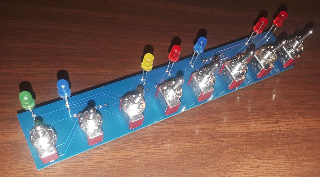
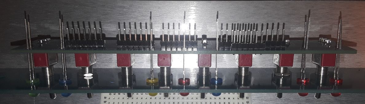
Please refer to the images for additional detail while assembling the panel interface board components.The board will be assembled in stages, to assure alignment, and to enable the builder to handle the multitude of individual components to be interconnected. First the eight switches are installed loosely on the back of the dress panel PCB. Only one nut, and no other hardware should be used. They should be loose enough that the switches may rotate, but not rock back and forth in the holes. There are SIX STANDARD SPDT switches, and TWO SPDT switches with a CENTER-OFF POSITION. The two center-off switches must be installed at the DENSITY and the BANDWIDTH locations on the right side of the panel. ALL SWITCHES must have the locating key, or groove, facing the BOTTOM of the panel BEFORE SOLDERING!
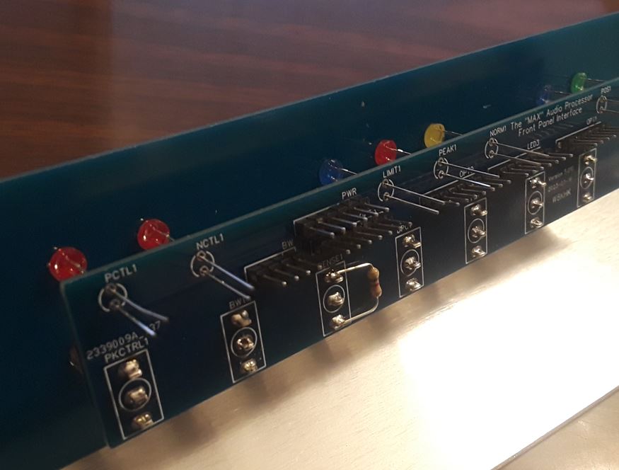
Prepare the front panel interface with the required dupont pin headers, by installing them on the SILKSCREEN side of the board, and soldering them on the BLANK side of the board that has no legends or white markings of any kind. While there may be others, the minimum header requirement will be a four-pin header to interface the BANDWIDTH switch, three six-pin headers for switch wiring to OPT1, OPT2, and OPT3 headers, either a three or six pin header for the panel POWER connection, and a seven pin header for the LED display array. (Only three wires are needed for panel power; pin 1 for -5 volts, pin two for ground, and pin 3 for + 5 volts, supporting the Peak Control LEDs on the right side of the front panel.)
For six-pin headers, there may be seven pads, but only six are used, pin one through six active, pin seven dormant. The pin one location is always to the left of the processor, and you will be viewing the silkscreened interface PCB from the back, so pin one from that view will be on the right. Put another way, the ID label for the pin-one end is always adjacent to the silkscreen header ID legend. When the ribbon cables are run from the interface board to the main board, they run straight back with no fold or flip, so pin one is always on the left when viewed from the front of the assembled processor.
Once the headers are installed and the switches are placed in the dress panel, (carefully ensuring the key notch on the switch threaded shaft is pointing DOWN toward the bottom of the panel). Of the eight switches, two have a center-off position, while the others only have an up and down position. Install the center-off switches at the "OPEN MID DENSE" density position and the "NARROW MED WIDE" bandwidth position. The interface PCB is placed on the switch contacts, with the non-silkscreened side of the interface PCB facing forward toward the switches.While putting pressure on the board to ensure it is as close as possible to each switch, solder only the center (common) terminal of each switch to the interface PCB.
Attach the switch board to the front panel, and securely fasten all eight nuts. Then push the LEDs forward, such that each is inserted securely and evenly through the openings in the front panel. Solder the LED wires, and clip the excess leads. You now have a completed assembly that may be interconnected to the main board, and it may also be easily disassembled if ever a component needs to be replaced.
Additional notes for rack mount chassis builds:
The rack mount chassis includes an envelope labeled "panel mounting hardware". There are five flat-head phillips machine screws and five nuts with captive lock washers. You will only need four, but sometimes the carpet steals small hardware and never gives it back.
The four screws will be used to attach the Bud Industries aluminum panel to their 1U rack enclosure. The front side of the panel must be countersunk, such that the screw heads are flush with the front surface. A countersink bit for this purpose is available for less than $2 at Harbor Freight, or a bit more at Lowes, Home Depot, or your local Ace Hardware.
The second step is to tape the dress panel to the aluminum panel, in a manner that it cannot shift in position. Then take a fine-point sharpie pen and mark each hole location as a circle on the aluminum panel. Remove the tape as soon as possible so it does not leave sticky residue on the dress panel.
Next, carefully center-punch all the hole locations on the aluminum panel. Location does not have to be perfectly centered, as the holes may be drilled slightly larger than the switch and LED diameters.
Using a small bit, drill the pilot holes at all centerpunched locations. Do NOT enlarge any holes to full size until later.
Temporarily mount the panel on the enclosure, using the four flat head machine screws. Verify the countersink is deep enough such that the screw heads are flush with the panel, otherwise the dress panel will be warped when attached later.
The two switches at the ends of the panel must be installed through three layers, the enclosure mounting tab, the aluminum panel, and the dress panel. In order to maintain proper hole alignment, using the small bit, drill a hole in each enclosure mounting tab, using the hole in the aluminum panel as a guide. Make sure this hole is centered vertically, and aligned as closely as possible with the holes in the dress panel. Next, enlarge these two switch holes with a 1/4" bit. Performing this operation with the panel bolted to the enclosure ensures matching alignment.
Now the aluminum panel may be removed from the enclosure, and all other holes drilled to the same, or slightly larger, size as the holes in the dress panel. The dress panel can now be attached to the aluminum panel with two switches on the ends, and the location of all other holes may be verified, and any that are too far off-center may be marked on the back side of the aluminum panel, then further enlarged for proper clearance after removing the dress panel from the aluminum panel.
The panel is now ready to perform the switch and LED soldering operation with the front panel interface board, This is most easily accomplished before the front panel is mounted permanently on the enclosure. Finish that operation, then remove the switch and LED assembly from the panels, then continue with the next step below.
When ready to mount the panel to the enclosure, start by attaching the panel with the four flat head screws, just finger tight. Pre-wire any Dupont or JST wires to the mic/line switch (typically connected to the INSW header) and pre-wire the power switch to lengths of hook-up wire, long enough to reach the desired power connections. Then mount each switch assembly to the enclosure and both The aluminum panel and the dress panel layers. It is difficult to wire the switches after mounting in the edge location of the enclosure. Now tighten all mounting screws and switch nuts, being careful to keep the switches vertical with the key notch at the bottom.
Next, mount the input and output level pots to the panel. These may also be pre-wired to Dupont or JST cables, then attached to the panel.
Last, the pre-assembled switch and LED board may be mounted to the panel. Either one domed washer, or no washer at all, will provide the proper reveal for the switch threads, allowing one nut to be attached and tightened. The dome washer should have the convex domed side facing the front panel, thus centering the device in the hole of the panel. This completes the front panel assembly process.
Voltage Regulator (U301, U302, U303,U304) Installation:
If the regulators are heat-sinked in this manner, the negative regulators must be insulated from the metal enclosure. It is actually preferable to insulate all four regulators, in the interest of eliminating any ground loops. (There should only be one ground point to the chassis, and that should be at the lowest-level input connector. Considering the input power connector passes AC to the on-board rectifiers, the common power input lead should also be isolated, and not grounded to the enclosure.)
Connecting an A.C. power supply:
The MAX processor circuit includes a full-wave bridge rectifier and a series of regulators for both the positive
and negative busses. Builders have the option to either use a chassis mounted transformer inside the cabinet or an
external "wall wart" supply with power brought in using an insulated barrel connector.
Some important information regarding power transformers:
Examples include:
Examples include:
Examples include:
Perform enclosure layout plan; mark locations and drill for all
components with these considerations
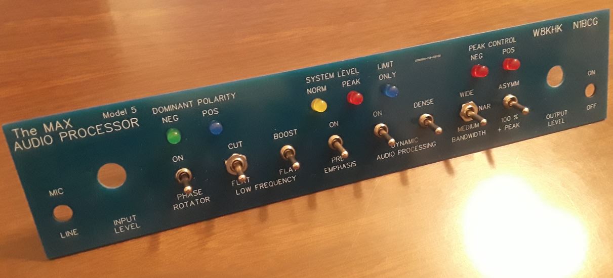
A suggested front-panel layout might include a row of option switches
low on the panel, and input gain potentiometers and other controls above the row of switches. Left would be the
two microphone input gain controls, and to their right the line input gain controls. Far right might be the
bandwidth and compressor controls.
The five LED indicators may be grouped in a vertical or horizontal arrangement. The blue LED indicates predominant
negative peaks in the mix, while the green indicates predominant positive peaks, which of course are preferred in
AM transmission. The yellow LED indicates normal input level to the compressor, and should be illuminated almost
continuously while talking, and the red Peak LED indicates the compressor is in operation and it should be
illuminated occasionally. Note: Vertical orientation appears similar to the familiar traffic stop-light configuration,
and thus is easily interpreted.
Plan to install connectors near to their respective headers on the printed circuit board. For example, when viewing
the enclosure from the rear, place the output connectors on the left, the line inputs in the center, and the
microphone inputs on the right. The power connector should be near the far left, as distant from low-level microphone
inputs as possible. If using an external AC transformer for a power source, be sure that the common lead is NOT
connected to the chassis or enclosure, thus eliminating one source of "Ground Loops".
Be sure to allow for clearance between board and components entering from the front and rear panels. This can be
accomplished by allowing sufficient vertical clearance between bottom of panel component, and the devices which rise
above the surface of the PC board.
Review locations of connection headers on board to allow easy access for wiring after the connectors and controls
are installed. If an over-sized enclosure is chosen, for example, a 1U rack enclosure, then front and rear panel
components may be far removed from the circuit board, and clearance conflicts are virtually eliminated. For smaller
enclosures, clearance requirements should appear rather obvious. Connection cables may be groups of wires, as needed,
with the exception of the high-impedance microphone input for ceramic, crystal, i.e. D-104 microphone input connections.
This low-level, high impedance connection requires shielded cable to minimize hum and noise. |
||||||||||||||||||||||||
|
Prepare a careful, symmetrical and aesthetically pleasing layout, then
punch and drill for
Note: Connectors may be any combination of XLR, TRS, RCA, or terminal strips, as desired. XLR and TRS connectors may be
connected in parallel to add flexibility and eliminate the need for adaptors.
Mount all components
Cut wire and/or use "Dupont wires" to solder or plug each component wire to respective headers on the board. |
 |
 |
|
MAX Audio Processor - Calibration Please review the steps outlined on the Calibration page to be sure your MAX Audio Processor is functioning correctly before use. |
|
MAX Audio Processor - Setting It Up
NOTE: Avoid using headphones to judge the effect of the Phase Rotator as mentioned above in the circuit description.
Pre-emphasis is beneficial in almost every application of the MAX Audio Processor in order to overcome the effects of narrow bandwidth receivers. It also boosts the important "presence frequencies" to improve clarity. The boost of higher frequencies can be adjusted using the Bandwidth controls discussed below.
With this done, a positively polarized asymmetric waveform could gain several dB in perceived loudness. By contrast, a negatively polarized asymmetric waveform would have the same perceived loudness as when both halves of the audio cycle. It's now fairly important to ensure that your audio source (microphone) is connected so that the green Dominant Polarity LED lights up more than the blue LED in order to take advantage of this modification (click image for a larger view).
Interestingly, the amount of audio energy processing is the same whether Dynamic Processing is on or off. The difference is that background noise is *not* processed when Dynamic Processing is on, thus it is the highly recommended setting.
A companion function controls the density of the audio by setting the aggressiveness of the processor. When set to "Dense", the processor speed is highest while "Open" gives a much more natural sound. The effects are most pronounced when the Dynamic Processing is off while offering more subtle control when Dynamic Processing is on. This allows users to find the optimal combination for their needs.
The transmitted bandwidth might be limited by the transmitter. In this case, the bandwidth setting will only have an effect at narrower settings. It's also important to consider the frequency response of receivers where most are far more limited than even the wide (7 kHz) setting of the MAX Audio Processor. Focusing the transmitted audio into a narrower bandwidth can actually increase perceived loudness.
* Balanced, High Level - Connect to the + (pin 2) and - (pin 3) output terminals.
* Unbalanced, High Level - Connect the shield to G (pin 1) and the hot lead to either the + (pin 2) or - (pin 3) output terminal depending on the polarity needed for the AM transmitter. The + terminal should be used by default for SSB or FM transmission.
* Unbalanced, Low Level - Connect the shield to G (pin 4) and the hot lead to the V (pin 5) output terminal. The low level trimpot R193 on the board can be used to adjust this output from zero (center setting) to any microphone or consumer unbalanced level by adjusting from the center in the direction that provides the desired polarity and level.
NOTE: Some applications will require a D.C. block such as when connecting to a transmitter designed to be used with an electret or condenser microphone. In this case, connect the hot lead to C (pin 6). The polarity and level adjustments are made the same way as when using pin 5. Use the C (pin 6) connection unless you are very sure that there is no need for D.C. isolation.
|