 |
 |
| The MAX Audio Processor For Amateur Radio, LPAM, And Podcasting | |
| HOME ||| GALLERY ||| ASSEMBLY ||| CALIBRATION ||| CONNECTIONS ||| MODS ||| SCHEMATICS ||| AVAILABILITY ||| CONTACT ||| LEGACY INFO |
| Revision Date: 230912
Information contained on these web pages copyright W8KHK / N1BCG. Amateur or individual use is encouraged. |
|
MAX Audio Processor - Schematic Diagrams
The Schematic Diagrams for the MAX Audio Processor consist of six pages in .PDF format, linked together as a single file.
Click the link to open and view the schematic PDF file in your browser. The PDF file will be displayed in a new tab or window. Right click on the link to save the schematic PDF file to your local drive. Processor Schematic Version 500 PDF |
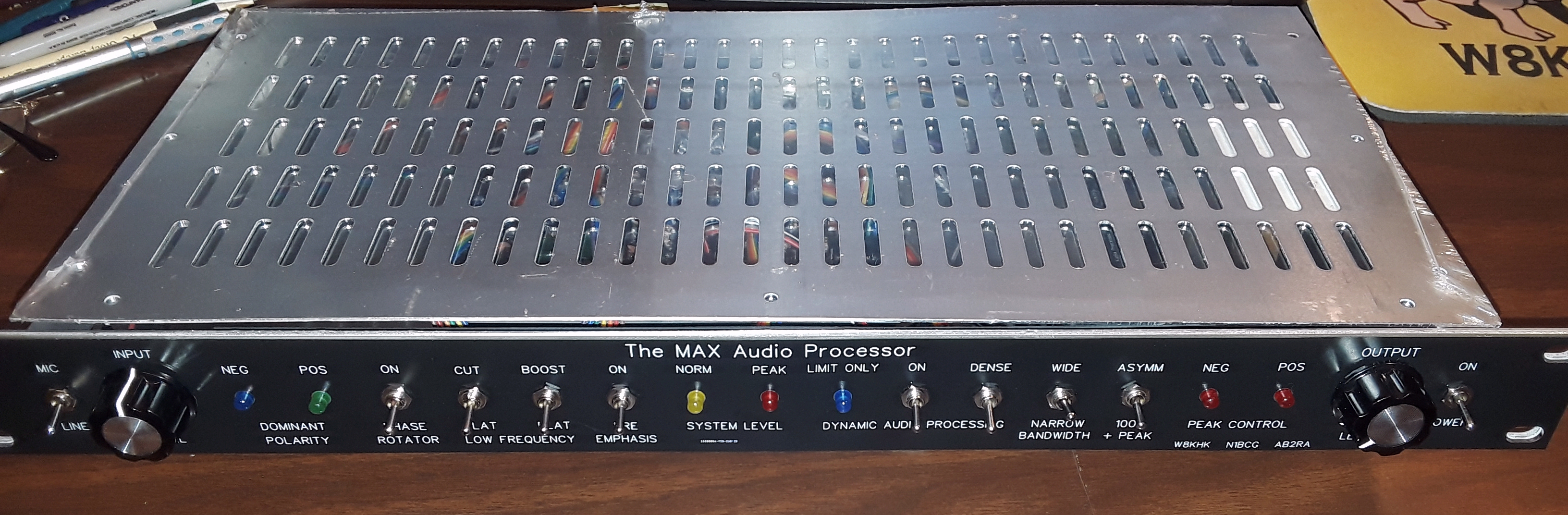
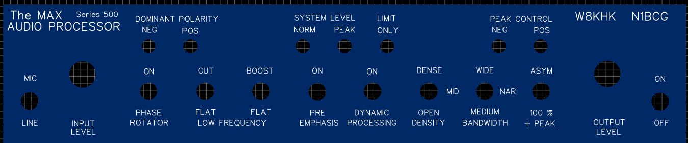
| MAX Audio Processor - Front Panel Images |
LED and Switch Front Panel Interconnect PCB Schematic (Type 1)
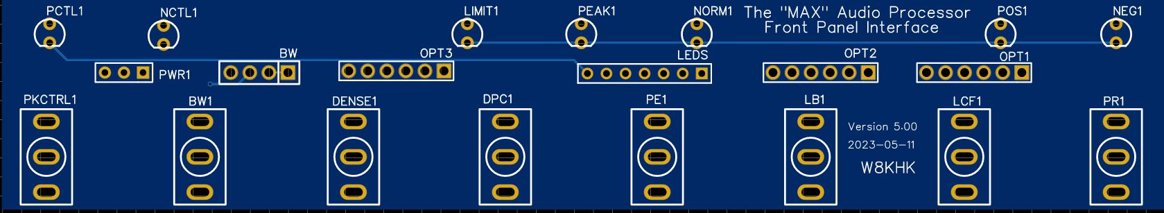
LED and Switch Front Panel Interconnect PCB Schematic (Type 2)


LED and Switch Front Panel Interconnect PCB Schematic (Type 3)


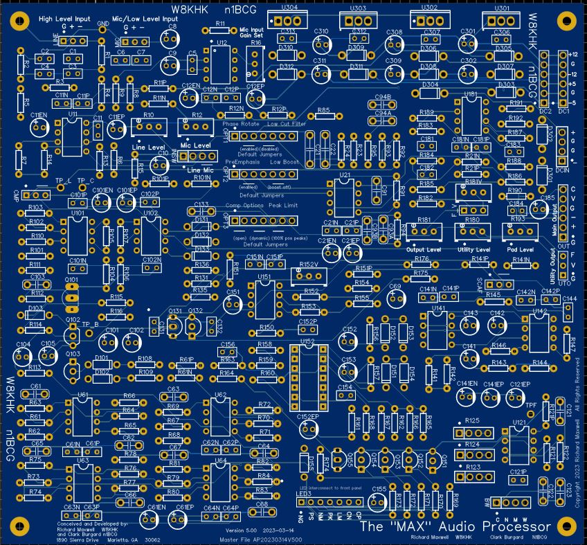
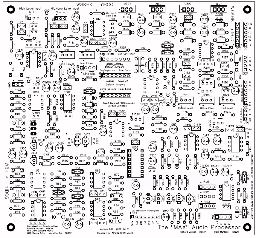
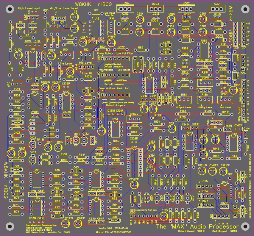
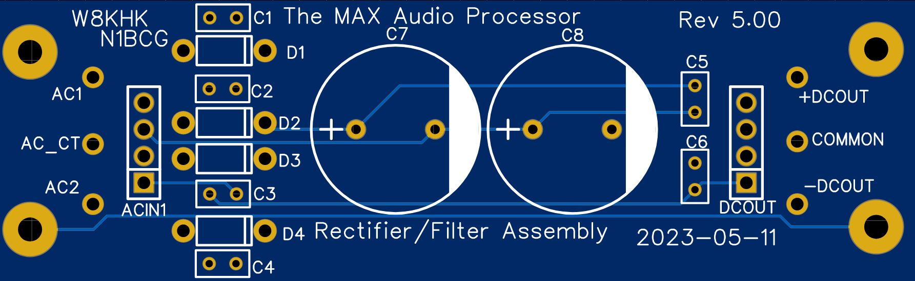
| MAX Audio Processor - Circuit Board Images |
 |
 |
 |
|
MAX Audio Processor - BOM and Parts Information
The Bill of Materials and detailed parts lists are available here. The BOM simply lists the components required, by group (capacitors, resistors, etc.) in value order with the required quantity of each device. The detailed parts lists are offered in three formats: 1) Ordered by component value to organize and inventory the parts 2) Ordered by device number as listed in the schematic diagram 3) Sorted by Function as used in each logical module of the processor In addition to providing parts value and quantity, the detailed parts lists include special notes to enable configuration and customization of the various processor sections. ALL PARTS in the parts list should NOT be installed indiscriminately. Please review the details to determine which parts should be installed to meet your desired goals. |