Audio Inputs - The MAX Audio Processor is designed to prepare the audio provided at the input for transmission in all voice modes with an emphasis on being clean and loud. The best results will be achieved by starting with input audio that is both unprocessed and unequalized. Microphones with a smooth frequency response are ideal, but that doesn't mean that an expensive studio microphone is required. In fact, even a modest music store microphone will work well as will nearly every microphone with a balanced XLR output. Note that some microphones require phantom power, typically 48 Volts, in order to work. The MAX Audio Processor does not have a phantom supply so an external power source would be needed. It is also possible to connect a microphone with an unbalanced cable (hot lead & shield) although the impedance should be set to "low" if that is an option.
Audio mixing consoles with either a consumer level (-10dBm) unbalanced output or professional level (+4dBm) balanced output will work very well with the MAX Audio Processor as an audio source. This allows the use of multiple microphones and most audio mixers have phantom power available.
Microphone (-60 to -40 dBm) Connections - The circuit board has a header marked "MIC/Low Level Input" with three connection pins: "G", "+", and "-". The standard is to use a chassis-mounted female XLR connector with the "+" pin connected to terminal 2 and the "-" pin connected to terminal 3. If shielded cable is used then the shield would connect only to the "G" (Ground) pin on the circuit board header and would be left unconnected at the XLR jack.
Unbalanced microphones typically use a chassis mounted 1/4" phone jack. Since the shield is grounded to the chassis through this jack, the center conductor would connect to the "+" pin of the "MIC/Low Level Input" circuit board header. The "-" pin of the input header should be jumpered to the "G" pin.
See the CALIBRATION section for information on setting gain of this microphone input.
Consumer Level (-10dBm) Unbalanced Connections - There's some flexibility as both the "MIC/Low Level Input" and "High Level Input" can accommodate this level input and the "G", "+", and "-" header pins are used the same way for either input.
Unbalanced line inputs typically use a chassis mounted "phono" or "RCA" jack. Since the shield is grounded to the chassis through this jack, the center conductor would connect to the "+" pin of either input. The "-" pin of the input header should be jumpered to the "G" pin.
See the CALIBRATION section for information on setting gain of these inputs.
Professional Level (4 to 8 dBm) Balanced Connections - The circuit board has a header marked "High Level Input" with three connection pins: "G", "+", and "-". The standard is to use a chassis-mounted female XLR connector with the "+" pin connected to terminal 2 and the "-" pin connected to terminal 3. If shielded cable is used then the shield would connect only to the "G" (Ground) pin on the circuit board header and would be left unconnected at the XLR jack.
See the CALIBRATION section for information on setting gain of this microphone input.
Audio Outputs - The MAX Audio Processor can accommodate a range of transmitter inputs ranging from -60 dBm unbalanced microphone to 8 dBm balanced professional levels.
Microphone (-60 to -40 dBm) Connections - This can be done, but using higher level connections (see below) is preferred to minimize the risk of noise or R.F. pickup. The "Main Output" header on the circuit board has pins marked "G", "V", and "C". Audio at the "V" and "C" pins is derived from the high level output through a balanced attenuator and provides a continuously adjustable range from -20dBm with inverted polarity through a null output to -20dBm with non-inverted polarity. Microphone level inputs can easily be accommodated using this output which also includes a D.C. blocking capacitor (terminal "C") for microphone inputs with a bias voltage.
For example, the output level is minimum when trimpot R193 "Pad Level" is centered. To set the output, adjust the trimpot in either direction until the output is approximately the same as a microphone would be if connected to that input. If it turns out that the polarity of the audio is reversed, adjust the trimpot in the other direction (back through no output) and continuing until the level is correct again. This position will provide audio of the opposite polarity.
NOTE: Some transceiver microphone inputs are designed specifically for desktop or handheld microphones where the only connection is at the microphone jack. This will be apparent if a feedback-like oscillation occurs when the microphone gain on the transceiver is increased even with no audio input. This was discovered when interfacing to the microphone jack on an iCom 751 and 751A (although other models did not exhibit this anomaly).
A different connection method may be needed for eliminating ground loop hum or other noises when connecting the MAX output to an unbalanced input, such as a microphone input. The MAX is equipped with a low level output with a D.C. blocking option for this purpose but in some cases it is not possible to connect the audio ground connection on a mic jack to the shield of the cable from the MAX without getting ground loop noise.
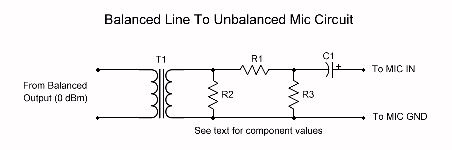
The circuit shown below uses an audio isolation transformer followed by an attenuator and then a D.C. blocking capacitor which will effectively couple the high level (0 dBm) balanced output of the MAX to an unbalanced microphone input.
|
The transformer (T1) can be a 600:600 or a common 1k to 8 Ohm speaker output device. For the latter, connect the full 1k primary to the balanced output of the MAX for greatest step-down attenuation.R1 can be around 22k when used with a 1:1 transformer or 2.2k if a 1k to 8 Ohm speaker transformer is used. R2 is optional and is chosen to properly load the secondary of the transformer for flattest frequency response. R3 is 180 Ohms. C1 can be between 1uf and 4.7uF at 16V and is purely for mic inputs that also have a D.C. voltage on them for powering electret microphone elements.
|
|
|
| The microphone gain is controlled using the adjustment on the rig just as it would be if a handheld mic were used. The balanced output of the MAX would be set for around 0 dBm but could be adjusted to match the circuit levels to typical microphone levels for each rig.
|
Direct To Modulator (-20 to -10 dBm) Connections - Many transmitters with microphone inputs also have a provision for connecting to the modulator, typically through a rear panel accessory jack. This is by far the preferred method as there is the least amount of circuitry between the output of the MAX Audio Processor and the modulator. Users of these transmitters should check their owners manual for information on connecting an audio input in this way.
The required input level will vary depending on the transmitter and power level. If -10dBm or less is needed then the method described above for use with a microphone will work except that trimpot R193 "Pad Level" will have to be adjusted to a higher setting. If more output is needed then adjusting trimpot R181 "Output Level" should help. If it turns out that the output polarity is wrong (most noticeable with AM) then turn trimpot R193 down past the null (no output) and keep turning in that direction until the output increases to the proper level again. It will now have the opposite polarity.
Professional Level (4 to 8 dBm) Balanced Connections - This is done using the "Main Output" header on the circuit board using the "+" and "-" pins. These would typically be connected to a chassis mounted male XLR jack with the "+" pin connected to terminal 2 and the "-" pin connected to terminal 3. If shielded cable is used then the shield would connect only to terminal 3 on the XLR jack.